
Reactive Load Forecasting methods
In this article we will discuss abbout the reactive load forecasting methods. we will also studied about the series compensation shunt compensation, capacitor planning etc.
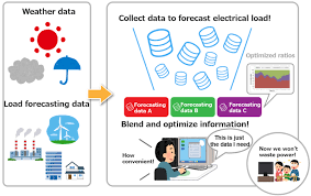
Reactive Load Forecasting Method
The planning criteria for reactive load forecast may be adopted as follows:
- Reactive power should not be transported over long distances.
- In normal intact network situations, reactive power should be produced and consumed locally.
- The network should be operated at upper voltage limits in high load conditions to achieve higher stability margins and reduce active and reactive power transmission losses.
- The amount of reactive power reserves should be sufficient to ensure acceptable transmission capacities in tie network during system disturbance conditions.these kind reactive load forecasting method provide. There are two important aspects, which distinguish reactive power planning from the planning of active power:
- Transmission of reactive power over long distances will have both active and reactive power losses and voltage drop. Compensation to maintain reactive power balance in an area must consequently be provideds in the vicinity. Reactive power is in this respect a more local problem than active power.
Reactive power Sources.
- Reactive power is generated or absorbed by all major components of a power system generators, transformers, HVDC converters, lines, loads, and reactive power compensating devices.its provide usefull data in load forecasting method.
- Reactive power compensation devices such as capacitors, reactors, synchronous condensers etc. are installed to improve reactive power balance, voltage control, and system stability including damping of power oscillations.
- The future UHV and EAV transmission development will not see much progress of shunt reactors and shunt capacitors and synchronous condensers. Static VAR compensators, based on power electronics will have large development in this area for transmission level..
Series Compensation
For long lines, series compensation is used to increase the permissible loading, which is limited mainly by the transient stability. The following factors should be consider in the selection of series compensation requirements
- Steady state and transient system stability.
- Protection of series capacitors.
- Sub synchronous resonance.
Shunt compensation
Selection of shunt compensation requirement for EHV lines requires consideration of the following factors:
- Steady state over voltage during light load conditions.
- Dynamic over voltages.
- Switching over voltages.
- Resonance voltages from parallel lines.
Capacitor planning
- The low voltage nodes can be raised within operating limits by increasing the generation bus voltage beyond the usual upper steady state limits. The system voltage is allowed to operate above the normal limit for low load since the extra reactive power intake can jeopardize the generator stability and shunting. To meet the contingency, some of the system nodes may be operating at voltage experienced during the low load period. The bus voltage raise produces an effect similar to the transformer tap variation.
- Optimum capacitors can be decided considering both the transformers tap setting and the variable voltage-ceiling limit.
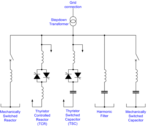
Criteria for Planning Static VAR System
- A static VAR compensator (SVC) is an automatically controlled supply of VARs. The supply of VARs is regulated by the thruster switching off reactors or capacitors in shunt with the transmission or distribution system. The result is that the voltage of the bus at the location of the SVC will be controlled. The response time of an SVC is in the range of a few cycles and can be switched as often as the control allows.

- Rapidly varying loads cause voltage fluctuations in the transmission or distribution system. Arc furnaces, welders, steel rolling mills, induction furnaces, cement mills, large pumps and compressors, mining shovels, woodchoppers, and electric traction loads are example of rapidly varying loads. Many times the industry with these loads. Many times the industry with these loads does not complain, but the other electricity-using consumers in the area do complain. SVCs are fast enough to stabilize voltage for the types of applications listen above and reduce or eliminate the consumer complaints of voltage fluctuations.
- Weak transmission and distribution systems with varying loads are one application, which could be served by SVCs.
If the load is constant, switched capacitors can usually supply the SVRs for the load and the line losses, thereby reducing current in the line, improving the power factor and thus regulating the voltage. If the load varies and the switched banks cannot be dispatched rapidly, enough to meet the load, then an SVC maybe required.
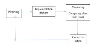
Dispatch ability in Power System Planning
Dispatchable generation refers to sources of electricity that can be dispatched at the request of power grid operators or of the plant owner according to market needs. Dispatchable generators can be turned on or off, or can adjust their power output accordingly to an order. This is contrast with non-dispatchable renewable energy source such as wind power and solar PV power that cannot be controlled by operators. The only types of renewable energy that are dispatchabl without separate energy storage are biomass, geothermal and ocean thermal energy conversion. these are provide information about the reactive load forcasting methods.
Dispatch able plants have different speed at which they can be dispatch able. The fastest plants to dispatch are hydroelectric power plants and natural gas power plants. For example, the 1,728 MW divorcing pumped storage power plants can reach full output in 16 seconds.
Although theoretically dispatchable, certain thermal plants such as nuclear or coal are designed to run as base load power plants and may take hours or sometimes days to cycle off and then back on again.
The attractiveness of utility-scale energy storage is that it can compensate for the indeterminacy of wind power and solar PVpower. During 2017, solar thermal storage power has become cheaper and a bilk dispatchable source. Earlier, affordable large-scale storage technologies other than hydro were not available.
The main reasons why dispatchable power plants needed are:
- To provide spinning reserves (frequency control).
- To prove spinning the electric power system (load following).
- To optimize the economic generation dispatch (merit order).
- To contribute to clear grid congestion (redispatch).
Frequency Regulation or Intermittent Power source
Change in the electricity output sent into the system may change quality and stability of the transmission system itself because of a change in the frequency of electricity transmited; renewable sources such as wind and solar are intermittent and need flexible power sources to smooth out their changes in energy production.

Backup for Base-load Generators
Nuclear power plants, for example, are equipped with nuclear reactor safety systems that can stop the generation of electricity in less than a second in case of emergency.
Hence these are reactive load forecasting methods. if you will find any incorrect in above article you must comment below in comment box.