Combinational Circuit Multiplexer and Decoder Working
In this article we will learn about the combinational circuit multiplexer and decoder working . we will know how the multiplexer work and we will also discuss about the decoder working.
Combinational Circuit Multiplexer and Decoder working
Combinational Circuits Introduction
In Digital Electronic Combinational logic circuits are circuits in which the output at any time depends upon the combination of the input signals present at that instant only, and does not depend upon any past conditions. A combinational circuit designed with individual gates can be implemented with SSI circuits that contain several independent gates. The numbered pins in the IC package limit the number of gates in an SSI circuits. Many combinational circuits are employed in the design of digital systems and are available in the form of MSI components. The following are the most important combinational circuit-type MSI components that are readily available in IC packages: (1). adders,(2) subtractor, (3) comparators, (4) decoders and encoders (devices that change data from one type of code to another) (5) multiplexers (selecting one of several groups of data), (6) demultiplexers (distributing data to one among several destinations), (7) parity generators/checkers and (8) code converters.
Multiplexer (data selectors) Introduction
The term ‘multiplex’ means “many into one.” Multiplexing is the process of transmitting a large number of information over single line. A digital multiplexer (XUX) is a combinational circuit that selects one digital information from several sources and transmits the selected information on a single output line. A multiplexer is also called a data selects one of many inputs and steers the information to the output.
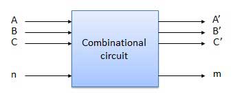
The multiplexer has several data-input lines and a single output line. The selection of a particular input line is controlled by a set of selection lines. The block diagram of a multiplexer with n input lines, m select signals and one output line. The selection lines decide the number of input lines of a particular multiplexer. If the number of n input lines is equal to 2m. The m select lines are required to select one of the n input lines for example, to select 1 out of 4 input of lines, two select lines, three select lines are required and so on. The multiplexer acts like a digitally controlled multiplexer switch where binary code applied to the select inputs, controls the data input that will be switched on to the output.
Data routing
Multiplexers can be used to route data from one of several sources to one destination.
Logic function generator
It can also be used to implement logic functions in sum-of-products from directly from a truth table without the need for simplification. The logic variables are used as the select inputs and each data input is connected permanently HIGH or LOW.
Control sequencer
A multiplexer can also be used as a part of control sequencer.
Parallel-to-serial converter
Digital systems that process data in parallel form take very less time. In order to transmit the information over long distances, the parallel arrangement is undesirable, as it requires a large number of transmission lines. Therefore, data in parallel form is converted to serial form using multiplexers.we have explain combinational circuit multiplexer and decoder working .
Demultiplexer (Data distributions) working
The word “demultiplex” means one into many. Demultiplexing is the process of taking information from one input and transmitting the same over one of several outputs. A demultiplexer is a logic circuit that receives information on a single input and transmits the same information over one of several (2m) output lines.
Application of multiplexer
Multiplexer circuits find numerous applications in digital systems. Some of the fields where multiplexing finds immense use are data selection, data routing, operation sequencing parallel-to –serial conversion, waveform generation and logic function generation.
Decoders Introduction
A decoders is similar to demultiplexer but without any data input. Most digital systems require the decoding of data. Decoding is necessary in applications such as data demultiplexing, digital display, digital-to –analog converters and memory addressing.
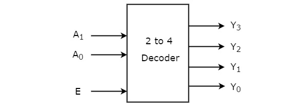
A decoder is a logic circuit that converts an n-bit binary input code (data) into 2n output lines, such that each output line will be activated for only one of the possible combinations of inputs.
In a decoder, the number of output is greater than the number of inputs. Here, it is important to note that if the number of inputs and outputs are equal in a digital system then it can be called converters, e.g. BCD to Excess-3 code, binary to gray and Gray to Binary code converters.
Hence these are combinational circuit multiplexer and decoder working . we have also discussed about the application of multiplexer. If you will find any incorrect in above article you must comment below in comment box.