Earthing of Power System
In this article we will know about Earthing of power system . we will also know about the earthing of power system equipment like grid resistance grid earthing and also studied about the generating station , sub-station
Earthing of Power System Introduction
The topic of earthing deals with the problems relating to conduction of electricity through earth. A number of points on every power system, from generators to the consumer’s installations, are earthed. The objects of earthing are:
- To ensure that all parts of equipment, other than live parts, do not assume a potential which is dangerously different from surroundings
- To allow sufficient current to flow safely to operate the protective devices.
To limit over voltage from neutral to ground and from line to grid.
Earthing Of Power System.
Earthing can be divided into neutral earthing and equipment earthing. Neutral earthing deals with the earthling of the system neutral to ensure system security and protection. Equipment earthing deals with earthing of non-current carrying parts of the equipment to ensure safety of personnel and protection against lightning.
Earthing Of Power System Equipment
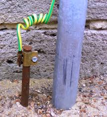
Earth electrode. A rod, pipe, plate or an array of conductors, embedded in earth horizontally or vertically. In distribution systems the earth electrode may consist of a rod, about one meter
long, driven vertically into the ground. For sub-stations and generating stations, an elaborate earthing system, known as earthing grid or earth mat, is used.
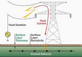
Resistance of earth electrode. The resistance offered by the earth electrode to the flow of current into the ground. This resistance is not the ohmic resistance of the electrode but represents the resistance of the mass of earth surrounding the earth electrode. Numerically it is the ratio of the potential of earth electrode, with respect to a remote point,to the current dissipated by it.
Step potential. The potential difference shunted by a human body between two accessible points on the ground separated by the distance of one pace, assumed to be equal to one meter.
Touch potential. The potential difference between a point on the ground and a point on an object likely to carry fault current (e.g. frame of equipment) and which can be touched by a person.
Earthing of Power System Generating Station and Sub-Station.
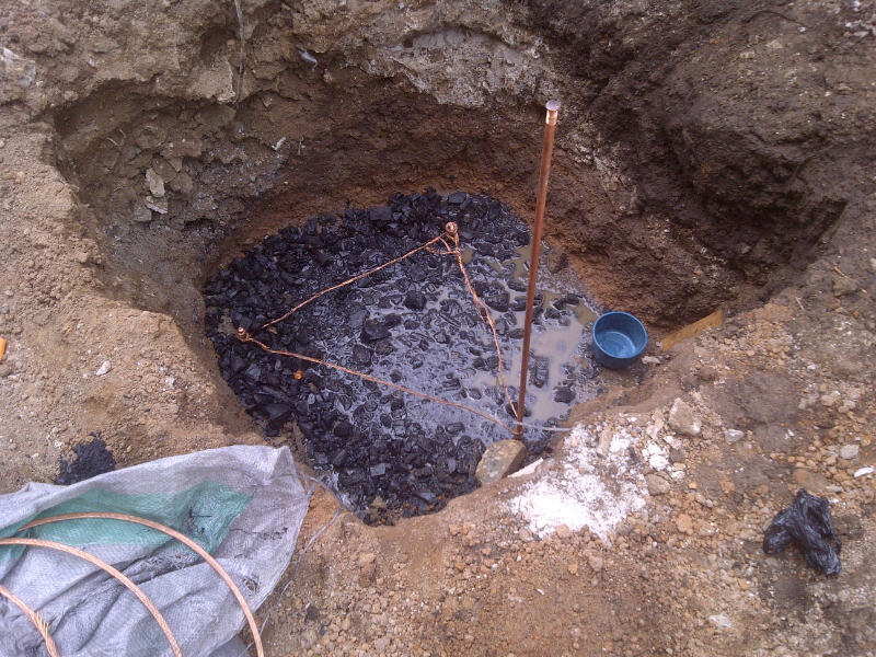
In sub-stations and generating stations it is necessary to make provision for earthing of neutral points, frames of all equipment and other metal work. The earthing system consists of an array of conductor’s biried horizontally at the depth of about 0.5m. Such an earthing system is called an earthing grid or an earth mat. It is customary to put vertical driven rods, each about 1m long, at some of the junction points . Selection of material and size of the conductors of the grid. Copper was commonly used as the ground electrode material. However due to high cost and poor availability of copper, especially in countries like India, steel is being increasingly used for this purpose. At present only steel is used.
The size of conductor should be such that the conductor would not fuse even under the most severs fault current and fault duration conditions and be mechanically strong. Where steel is used, an additional allowance for corrosion of the material should also be made. Strips are generally used as they can be more easily bent, bolted and welded as compared to round bars. Preliminary arrangement of grid conductors. To obtain a preliminary arrangement of grid conductors, it is necessary to have the layout of the sub-station. To have an earth mat of low resistance, the mat should enclose as much ground area as possible. A continuous conductor, therefore, should surround the sub-station area to enclose maximum area. a number of cross connections, lengthwise and breadth-wise, should be put in parallel lines to facilitate multiple connections to neutral points and equipment. Typical size of grid mesh is 5m*5m. Once the conductor arrangement is known, the total length of buried conductors can be calculated. Calculation of Grid Resistance.
The value of grid resistance should be less than 5000/I where I is the maximum fault current amperes. If the grid resistance. The value of grid resistance should be less than 5000/l where I is the maximum fault current in amperes. If the grid resistance is more than this value a revised design is necessary.
Connection to The Grid.. It is necessary to connect all the neutral points and the bases of generators, transformers, circuit breakers, isolators, switches, lighting arresters, instrument transformer etc. to the earthing grid by an independent connection in each case for this purpose a number of rises are taken from the earthing grid. Since the equipment may be situated at more than one floor, an earthing ring is put along the inside of the building walls at each floor. All equipment are connected to the earthing ring rings which are in turn connected, through the riser, to the main grid.
Neutral Earthing Of Power System
A number of methods exist for earthing the neutral point of generators and transformers. At one extreme is the grounded or isolated neutral and the other extreme is the solidly earthed neutral. in between the are various degrees of earthing through resistance, reactance or arc suppression coil.
Isolated Neutral Earthing Of Power System
As the name suggests an isolated neutral system operates with the neutral not connected to ground. In the event of line to ground fault on any phase, the healthy phases assume line to line potential. The fault current flowing from the faulty phase to ground returns to the system via the line to ground capacitance of healthy phases. This may give rise to intermittent arcing at the point of fault. This phenomenon, known as arcing grounds, may give reset to high voltages, about three to four times the system phase voltage, on the healthy phases and may cause further faults on the systems. in view of this the isolated neutral systems are not popular.
Solid Earthing Of Power System
Solid earthing (also known as effective earthing) means a direct connection of the neutral to earth. To be more exact a system is known as effectively earthed when the voltage of healthy phases, in the event of a line to ground fault, does not rise beyond 80%of the line to line voltage. Solid earthing is recommended when the maximum earth fault current is not likely to cause damage to equipment, cables etc. the only disadvantages of solid earthing is that in the event of a fault involving ground , the fault current is high. However due to the advent of high speed protection system and high rupturing capacity fuses, this disadvantage has been, more or less, overcome. Therefore most of the systems operate with solid earthing.
Resistance Earthing Of Power System.
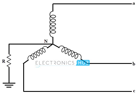
When it is necessary to limit the earth fault current the neutral is attached through a metallic or liquid resistor. Resistance earthing also improves the system stability under fault conditions. The resistance should neither be very low nor very high. A very low resistance makes the system similar to the solidly earthed system.
Hence these are the earthing of power system. If you will find any incorrect in above article you must comment below in comment box.