Induction Regulator Working
In this article we will learn about the induction regulator working and we will also know about the Static VAR compensation . we will discuss in detail about VAR system advantage and disadvantage.
Induction Regulator Working
An induction regulator is essentially a constant voltage transformer, one of winding which can be moved w.r.t. the other, thereby obtaining a variable secondary voltage. The primary winding is connected across the supply while the secondary winding is connected is series wit
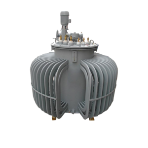
h the line whose voltage is to be controlled.
When the position of one winding is change w,r,t, the other, the secondary voltage injected into the line also changes. There are two types of induction regulators viz. single phase and 3-phase.
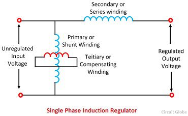
(1) Single-phase Induction Regulator Working
In construction, it is similar to a single phase induction motor except that the rotor is not allowed to rotate continuously but can be adjusted in any position either manually or by a small motor. The primary winding AB id wound on the stater and is connected across the supply line. The secondary winding CD is wound on the rotor and is connected in series with the line whose voltage is to be controlled.The primary exciting current produces as alternating voltage in the secondary winding CD. The magnitude of voltage induced in the secondary depends upon its position w.r.t the primary winding. By adjusting the rotor to a suitable positive, the secondary voltage can be varied from a maximum positive to a maximum negative value. In the way, the regulator can add or subtract from the circuit voltage according to the relative position of the two windings. Owing to their greater flexibility, single phase regulators are frequently used for voltage control of distribution primary feeders.
(2) Three- phase Induction Regulator Working.
In construction, a three-phase induction regulator is similar to a three-phase induction motor with wound rotor except that the rotor is not allowed to rotate continuously but can held in any position of means of a worn gear. The primary wingdings either in star or delta are connected across the supply. The secondary winding is wound on the rotor and the six terminals are brought out since these wingdings are to be connected in series with the voltage is to be controlled.
The induction regulator has the following advantages over a variable auto transformer:
(i) A continuous steeples variation of the output voltage is possible.
(ii) No sliding electrical connections are necessary.
However, the induction regulator suffers from the disadvantages of higher leakage inductance’s, higher magnetizing current, and higher leakage inductance’s, higher magnetizing current and higher costs.
Static VAR Compensation
Static VAR Compensatory (SVCs) are those which have no rotating parts and are employed for surge impedance compensation and for compensation by sectionalizing a long transmission line. These are also employed for load compensation where in these maintains constant voltage (i) under slowly varying loads. (ii) Load rejection, outages of generator, and line (iii) under rapidly varying loads e.g. as furnaces, rolling mills etc. these improve system stability and system power factor. Since reactive power flow is controlled by SVCs, these are employed for minimization of transmission losses and control AC voltage near HVDC converter terminal.
Overview of Static Var Compensation
A static VAR Compensator (SVC) is basically a parallel combination of controlled reactor and fixed shunt capacitor, and is capable of steeples adjustment of reactive poer over an unlimited range (lagging and leading) without any delay. Even though a fast response is usually desirable, but not essential for all operating condition of the systems. For instance, fast compensation is not necessary for system stability when other factors limit the stability of the system. In actual practice, the reactive current is restricted in both lagging and leading regions because of the current caring capacity of the compensator.
The reactor control is accomplished by an anti-parallel thyristor switch assembly. The firing angle of the thrusters controls the voltage across the inductor and thus the current flowing through the inductor. In this way, the reactive power draw by the inductor can be controlled. If Qcis the reactive power generated by the fixed capacitor Can QL is the reactive power absorbed by the inductor, the net reactive power injection to the bus will be
Q= Qc – QL
In SVR, QL is controllable and thus Q can be controlled. During light-load period, QL is made larger than Qc while during heavy load condition, QL is made smaller than Q
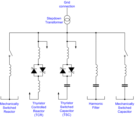
Types of static VAR systems
Many SVS schemes are in operation. Some of commonly used schemes are as follow: these are describe about induction regulator.
- Thyristor controlled reactor (TCR)
- Thyristor switched capacitor (TSC)
- Self saturated reactor (SR)
- Thyristor controlled reactor-Fixed capacitor (TCR-FC)
- Thyristor switched capacitor-Thyrister controlled reactor (TSC-TCR)
Hence these are induction Regulator working . SVS are also explain above if you will find any incorrect in this article you must comment below in comment box.