Working and Construction of Repulsion Motor
In this article we will learn about the working of repulsion motor. We will also know about the construction of repulsion motor.
Working and construction of repulsion motor
Repulsion is similar to an AC series motor except that:
1. Brushes are not connected to supply but are short circuited. Consequently, current are induce in the armature conductors by transformer action.
2. The field structure has non-salient pole construction.
For developed starting torque by adjusting position of sort circuited brushes on the commutator.
Construction of Repulsion motor
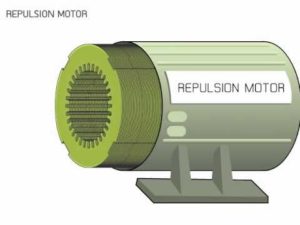
The field of stator winding is wound like the main winding of a split phase motor and is connected directly to a single phase source. The armature or rotor is similar to a DC motor armature with drum type winding connected to a commutator (not shown in fig.) However, the brushes are not connected to supply but are connected to each other or short circuited. Short circuited the brushes effectively make the rotor into a type of squirrel cage.
Principle of repulsion motor
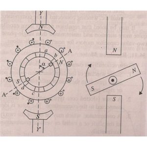
The principle of operation is illustrated in fig. which shows a two-pole repulsion motor with its two short-circuited brushes. The two drawings of fig. represent a time at which the field current is increasing in the direction shown so that the left hand pole is N-pole and the right hand pole is S-pole at the instant shown.
A) in fig. the brush axis is parallel to the stator field. When the stator winding is energized from single-phase supply EMF is induced in the armature conductors (rotor) by induction. By lenzs law, the direction of the EMF is such that the magnetic effect of the resulting armature currents will oppose the increase in flux. The direction of current in armature conductors will be as shown in fig. current flow from brush B to brush A where it enters the armature and flows back to brush B through the two paths ACB and ADB. With brushes set in this position, half of the armature conductors under the N-pole carry current inward and half carry current outward. The same is true under S-pole. Therefore, as much torque is developed in one direction as in the other and the armature remains stationary. The armature will also remain stationary if the brush axis is perpendicular to the stator field axis. It is because even then net torque is zero.
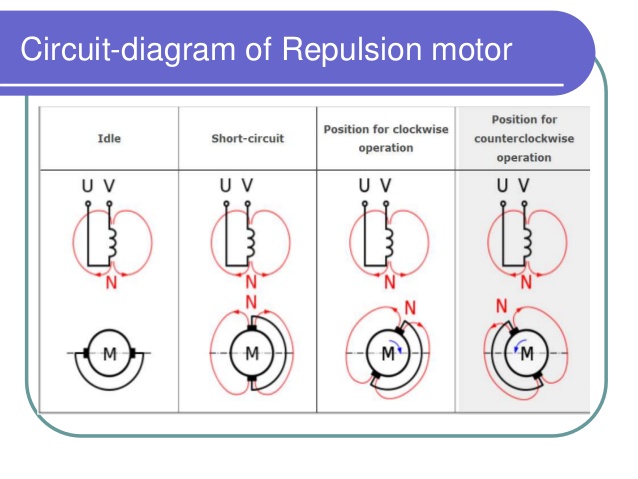
B. If the brush axis is at some angle other than 0 degree or 90 degree to the axis of the stator field, a net torque is developed on the rotor and the rotor accelerated to its final speed. fig. represents the motor at the same instant as that in fig. but the brushes have been shifted clock wise through some angle from the stator field axis. Now EMF is still induced in the direction indicated in fig and current flows through the two paths of the armature winding from brush A to brush B. however because of the new brush positions, the greater part of the conductors under the N-pole the opposite direction. With brushes in the position shown in fig. torque is developed in the clockwise direction and the rotor quickly attains the final speed.
Thus, repulsion motor may be made to rotate in either direction depending upon the direction in which the brushes are shifted.
Hence these are working and construction of repulsion motor .
For knowing more about the construction and working of repulsion motor.
For knowing more about the construction and working of repulsion motor.


